

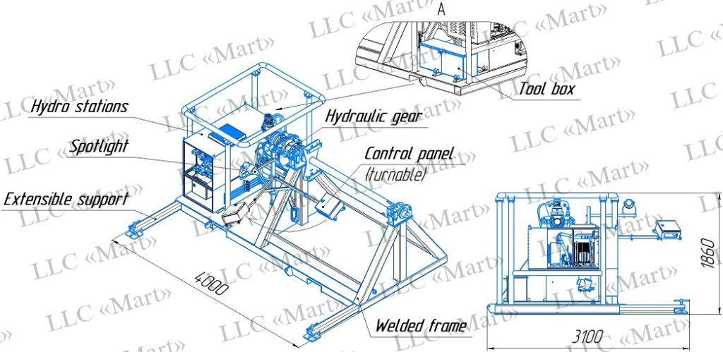
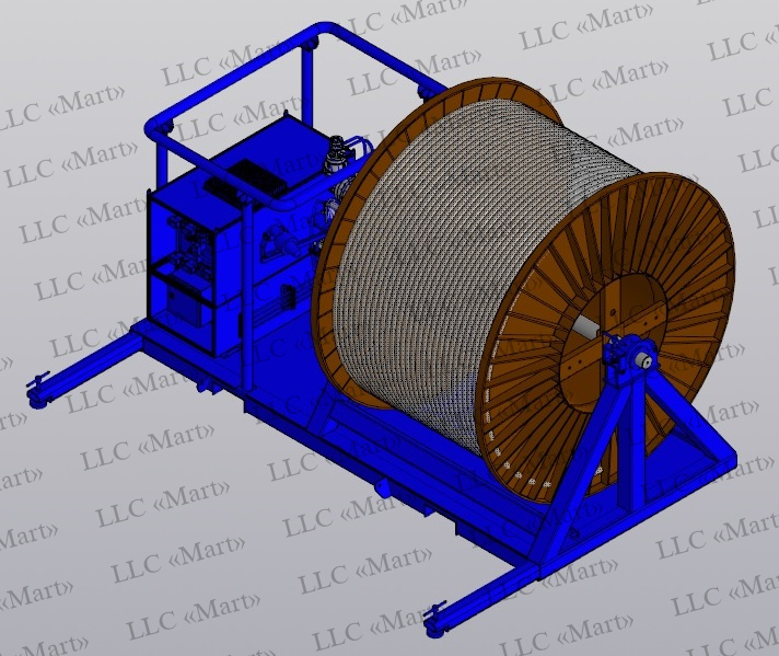


The installation is designed for rewinding / winding cable lines in the field during the installation / dismantling of the ESP with an adjustable feed rate.
Brief description of the construction
The installation consists of:
1. A welded frame with a hydraulically driven drum, with places for loader forks and extensible supports.
2. Hydro stations with hydraulic equipment
3. Control panel
4. Tool Box
Hydraulic Equipment:
- Float level indicator in explosion-proof design Remote control-3.1.250.K/2-Ex
- Explosion-proof temperature relay Exd-4GM-ZI-300mm-2C-T100-A2-1m-PG-PH-2S-GPL BDROSMA
- Explosion-proof valves according to IECEx for gas II 2G Ex db IIC T4 Gb, for dust II 2G Ex tb IIIC T154°C Db:
- Oil cooler in explosion-proof design 1ExdIIBT4
Electrical equipment:
- Electric motor in explosion-proof design 1ExdeIIBT4
- Stationary control panel in explosion-proof design 1Ex de IIC T6 Gb X IP66 ATELEX with explosion-proof controls:
-- Control of feed and reverse gears
-- Speed control
-- Emergency shutdown button
-- Colored light indicators of operating modes
-- Pressure and temperature indicators of the hydroelectric power plant.
- Portable control panel in explosion-proof design 1Ex db IIB+H2 T6 Gb IP66 with explosion-proof controls (control of feed, reverse gears, emergency shutdown button)
- VGM (SPY) plug and RGM socket (PY) in explosion-proof design 1Ex db IIC T6...T4 Gb, Ex tb IIIC T60°C...T135°C Db
- Supply cable KGN 4x10 (oil and gas resistant) 100m
- Lighting: street spotlight
Technical parameters:
| Torque | 2288 Nm. |
| Drum rotation frequency | 0-20 rpm. |
| Drum max dimensions | 96" х 69" (Diameter x Width) |
| Weight without drum | up to 3 tons . |
| Max load capacity | 15 t . |